Real-time data is the foundation of responsive, efficient, and traceable operations in smart factories. From torque values to counters and quality test results, your machines are generating valuable information every second. But how do you capture, interpret, and act on these insights across a complex ecosystem of interconnected industrial equipment?
If you’re currently using or considering DELMIA Apriso for your Manufacturing Operations Management (MOM) solution, you’re empowered by a robust tool called Machine Integrator (MI).
MI is a built-in component that connects physical equipment to your MOM system and enables bi-directional communication for process automation, monitoring, and traceability. Whether it's a high-speed packaging line or a semi-automatic torque tool, MI ensures that data flows from the shop floor to your MOM logic and back.
Machine integrator vs. equipment integrator
It’s important to establish if “machine integrator” and "equipment integrator" are the same thing and can be used interchangeably. While they can be, they are not always the same. Both relate to the process of integrating devices, machinery, or pieces of equipment into a cohesive system but MI has a broader meaning. Machine integrator can encompass equipment integrator and other system integrators.
|
Machine integrator |
Equipment integrator |
|
Refers to integrating different machines, equipment, and processes to create a functional system |
Refers to integrating individual pieces of equipment into a larger system or process |
|
Includes equipment and system integrators, and potentially even some OEM devices |
Focuses on connecting equipment to other systems, like MOM, MES or ERP |
|
Brings various pieces of machinery together to achieve a desired outcome, often in manufacturing or automation ecosystems |
Enables seamless integration and functionality in various manufacturing or OEM environments |
Why machine integration matters
As automation scales, more shop floor tasks are handled by machines. Operators increasingly supervise, staying in charge of maintenance tasks and changeovers. To gain full visibility and control over this environment, your MES and MOM systems must connect directly with machines.
Machine Integrator enables MOM solutions to:
- Collect live machine data
- Monitor performance
- Control equipment through command signals
- Store and analyze results for audits or OEE tracking
Without MI, machine data remains siloed, invisible to supervisors, untracked in reports, and decoupled from decision-making.
What does MI actually do?
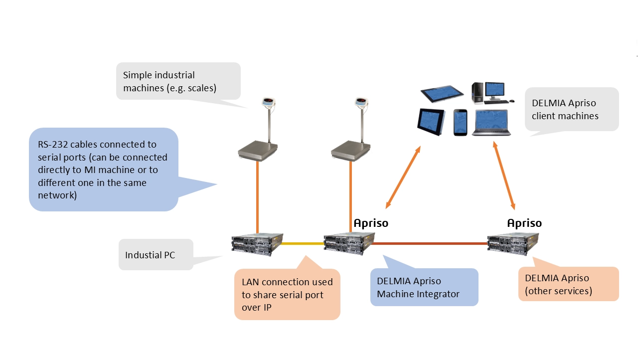
Machine Integrator enables two-way communication between machines and the Apriso platform through two main methods:
- Open Platform Communications (OPC): Common for PLC-connected devices
- RS-232: Used with legacy devices like simple industrial scales
Depending on the setup, MI can:
- Read machine values, such as torque, weight, or quality result
- Send control commands, including program number or torque threshold
- React to value changes, like alert on downtime, for example
- Run business logic when events occur
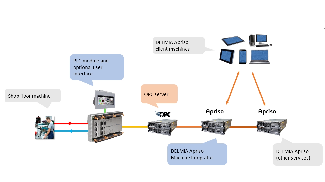
How MI fits into the landscape
Machine Integrator works within a layered system:
- Machine level: Sensors and actuators connect to PLCs.
- OPC layer: Windows-based OPC servers exchange data with PLCs.
- Machine Integrator: Acts as an OPC/RS-232 client and communicates with DELMIA Apriso.
- MOM logic: Executes stored procedures, operations, and UI responses based on machine data.
Common use cases
The following real-life use cases present how MI is typically used in real-world shop-floor environments.
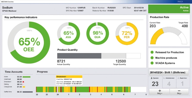
Production counters
MI captures real-time production counts directly from shop-floor equipment. These values are displayed on operator dashboards and used to track performance metrics such as OEE. When output falls behind expected targets, MI can automatically trigger alerts. This ensures greater visibility and faster response to production issues.
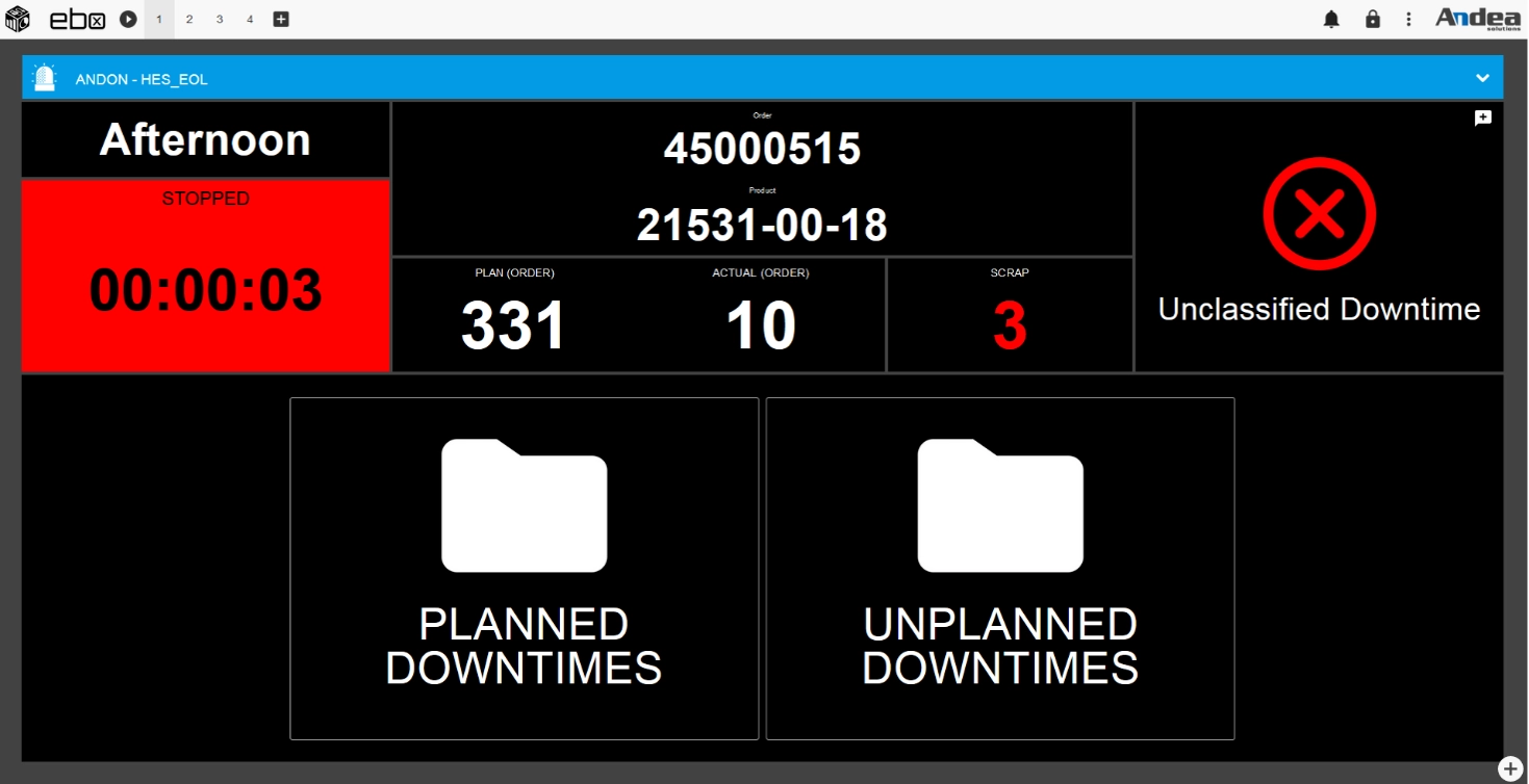
Machine status
MI continuously monitors machine states by interpreting PLC signals, making it possible to detect unplanned downtime or performance slowdowns. When a disruption occurs, alerts can be triggered automatically. This enables immediate awareness and faster root cause analysis, leading to significantly improved operational efficiency and equipment availability.
Electronic scales
In industries like chemicals and food, MI integrates with electronic scales to capture the actual weight of ingredients or components, ensuring the proper ratio before manufacturing the final product. MI compares these values to target weights, adjusting for factors like material potency or density. The entire weighing process is visualized on MOM screens for accuracy and operator guidance. All measurements are logged for traceability and compliance.
Semi-automatic tools
MI communicates with semi-automatic tools, like electrical torque tools, to ensure they are configured with the correct program for each production order. Parameters like torque value and rotation count are set automatically by the system. As tools operate, real-world values are captured and saved in MOM for traceability. This ensures compliance with quality standards and eliminates manual setup errors.
Quality assurance
MI connects with testing equipment, such as brake test stands, to capture quality control data directly from the source. Results are stored centrally in the DELMIA Apriso database, ensuring traceability and audit readiness. In industries with strict regulatory requirements, this data retention is essential as it supports long-term analysis and continuous improvement initiatives.
How to configure MI
The following steps cover a standard setup using the DELMIA Apriso Desktop Client.
Step 1: Install and launch MI
MI is installed by default on the DELMIA Apriso server. On other machines:
- Go to: http://yourservername/Apriso/Start/
- Click Set Up DELMIA Apriso Client
- Install the client to access MI
You can run MI in two modes:
- Console application (manually launched, best for testing, UI-enabled)
- Windows service (automatically managed, best for production, no UI)
Step 2: Define MI connectors
Each MI instance is configured as a Connector.
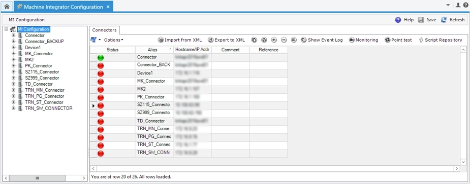
To configure:
- Go to the Machine Integrator Configuration screen.
- Right-click to add a new connector.
- Provide:
- Alias (must match MachineIntegrator.exe.config) as presented below:

- Hostname/IP address where MI runs
Step 3: Add data sources
Each connected OPC server or RS-232 device is a Data Source.
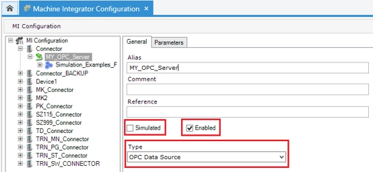
To configure:
- Specify type: OPC, RS-232, or Virtual (for testing)
- OPC: import points, define server, reconnect logic
- RS-232: define message structure and parsing formulas
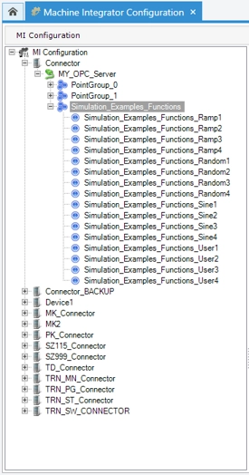
Step 4: Define Points and Point Groups
Points represent individual machine values. Group them by machine or line.
For each point you need to configure OPC DA Point Name:
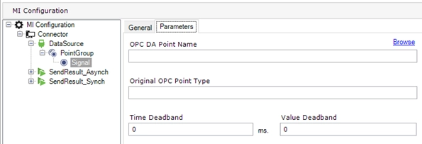
Additionally:
- Set data type
- Assign read/write access
- Provide alias and link to Equipment Feature (optional)
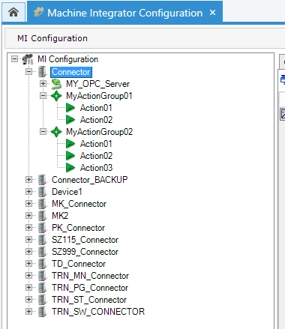
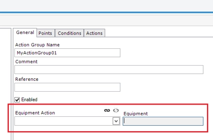
Step 5: Configure Actions and Action Groups
Action Groups define logic triggered by point changes, allowing the list of Actions to be executed.
To configure:
- Create Action Group under a connector
- Add points needed in conditions tab
- Add triggering conditions, for example, on point change
- Add actions:
- Stored Procedure (for quick inserts)
- Standard Operation (for business logic)
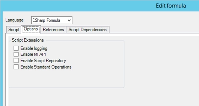
- C#/JS Scripts (for advanced conditions)
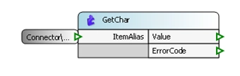
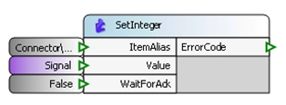
Step 6: Read and write point values using business components
Business Components are built-in functions specifically designed to handle point-level operations. They make it easy to access and manipulate Data Points within your logic. Use them for reading from and writing to MI Points within Process Builder.
This is the currently recommended and most widely practiced method, especially when developing new solutions. There is also a Step 7 alternative, which remains supported by DELMIA Apriso and may still be in use for legacy applications. However, for any new development, the functionality described in Step 6 should be the default go-to for interacting with MI Points in standard operations.
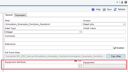
Step 7: Link to equipment features (is optional but recommended)
Avoid hardcoding point aliases. Instead link Points and Action Groups to equipment features for easier maintenance, scalability, and reusability across multiple machines, as well as support for abstraction in Process Builder.
To do it:
- Define Equipment Classes.
- Link Attributes and Actions to MI Points and Action Groups.
Usage scenarios
Once your Machine Integrator configuration is in place, there are several practical ways to use MI Points within DELMIA Apriso both in background logic and interactive user workflows. This makes MI not only a tool for visibility, but also a key enabler of real-time control and process automation on the shop floor.
Three ways to reference MI points
MI Points serve as the link between machine data and MOM intelligence, allowing for dynamic monitoring, responsive logic execution, and real-time updates across screens and processes. This makes MI not only a tool for visibility, but also a key enabler of extensive control and process automation on the shop floor.
There are three primary ways to reference an MI Point in your configuration or standard operations:
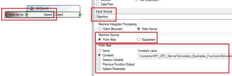
- Machine values can be written back to equipment either by MI itself, based on another point's value, or as a result of business logic defined in standard operations.
- Alternatively, you can reference the MI Point using an absolute path, e.g. Connector\MY_OPC_Server\..., or a relative path, which is only valid when the Machine Integrator instance runs on the same machine and when Client Side Processing is enabled.
- Another maintainable method is by using an Equipment Feature, which abstracts the technical path and promotes reusability.
Advanced integration scenarios
Depending on a use case, machine values can either trigger MOM logic, be retrieved on demand, or drive UI behavior. Choosing the right method depends on your deployment model and whether logic runs on the server or directly within the user's browser. The most common integration scenarios include:
- Machine-driven logic
- Machine state changes can trigger business logic.
- Requires properly configured points, connectors, action groups, and scripts.
- On-demand reading or writing machine values
- Used in background business processes.
- Inputs and outputs must be set to "Machine" type.
- Works with server-side logic defined in Process Builder.
- Real-time JavaScript-enabled UI monitoring
- Uses client-side processing to display and update machine data on user screens.
- Includes dynamic visual elements and scripting, like warning icons or auto-submit.
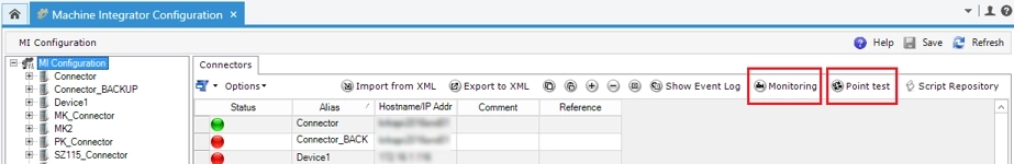
Monitoring, testing, and logs
To track all connector activities, statuses, and warnings, DELMIA Apriso provides two key tools via the configuration screen:
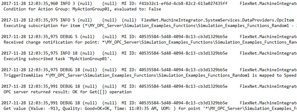
- MI Monitoring: View logs and system messages for each connector and point.
- MI Point Test: Manually send or read values from machines for testing purposes.
Moreover, MI supports both server-side and client-side processing for business operations and user interfaces. Use:
- Server-side for background jobs or logic-heavy tasks.
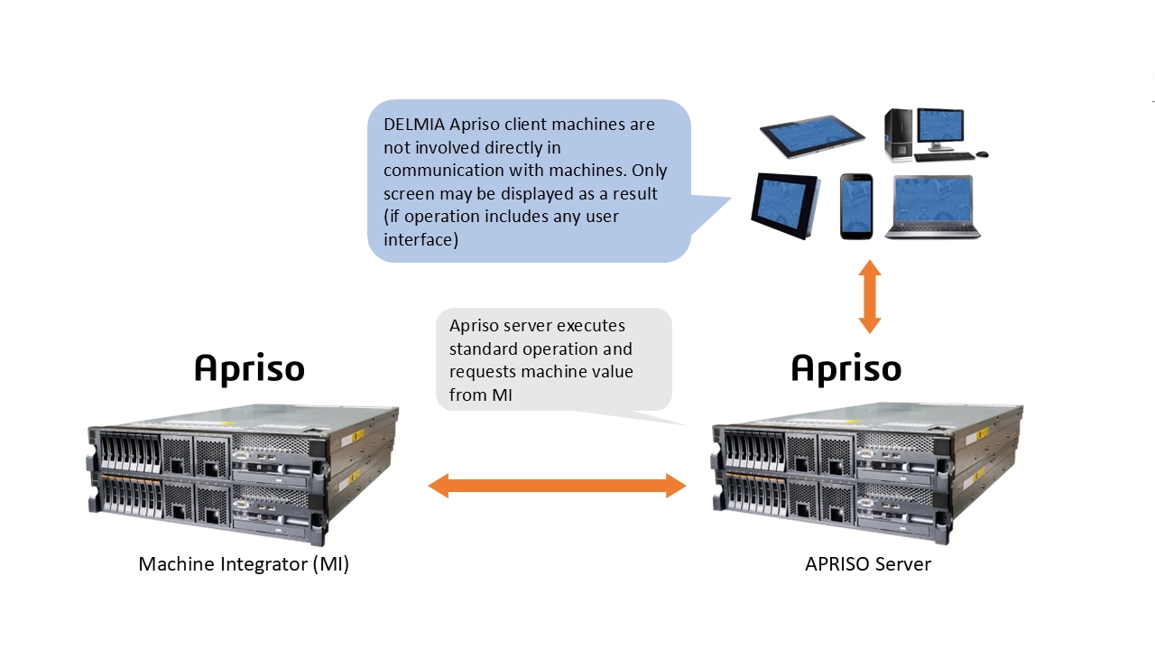
- Client-side for real-time screen updates (via JavaScript APIs or WebSockets).
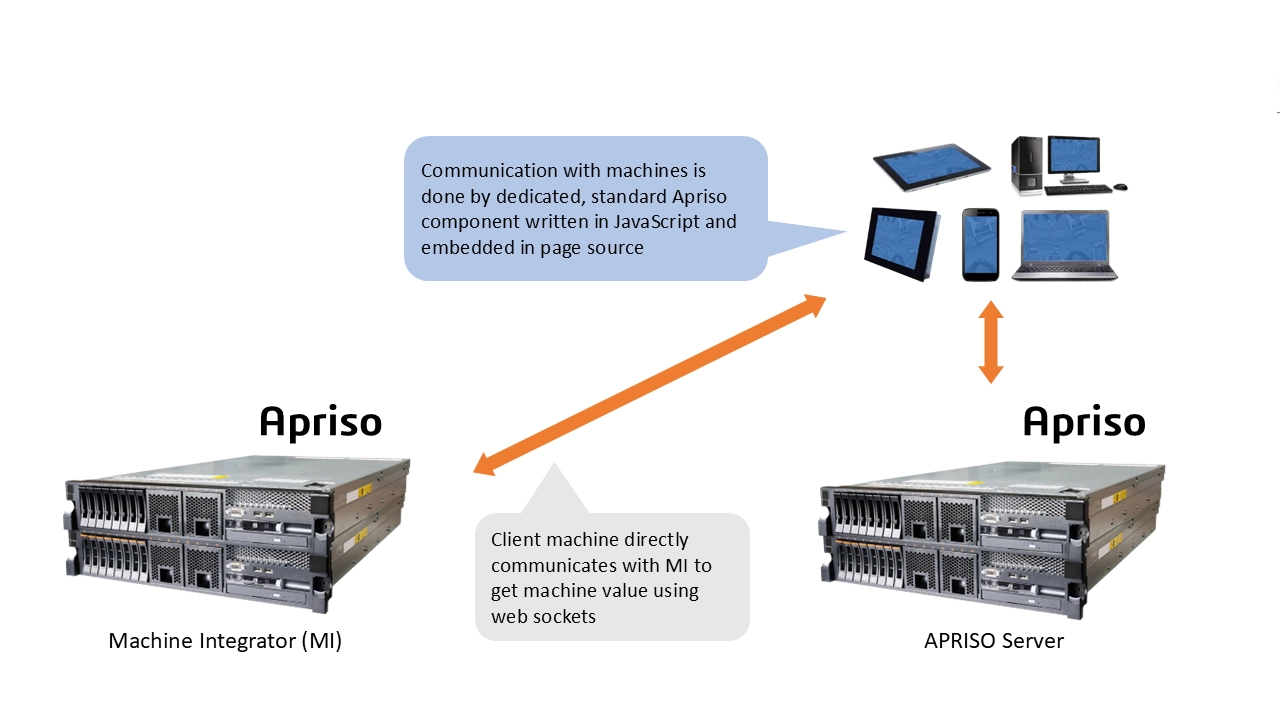
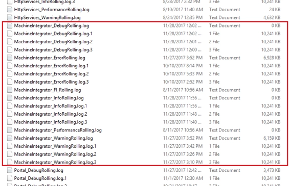
Custom scripts can make screens reactive—showing warnings, updating charts, or submitting actions automatically when values change. For in-depth diagnostics, logs are stored locally on the MI machine. The default path is C:\Temp\AprisoLogs\.
Best practices for configuring MI
The following are dos and don’ts for optimized and sustainable MI configuration:
- Avoid overloading action groups with too many triggering points.
- Use stored procedures for lightweight, high-frequency logic and fast, simple actions.
- Use standard operations without heavy logic for business-critical tasks and complex business logic.
- Avoid long-running and heavy logic inside MI in favor of background jobs when needed.
- Use Equipment Features over hardcoded aliases to decouple technical from business configurations, making abstraction and reusability easier and more efficient.
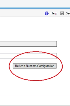
- Always refresh runtime configuration after changes by using “Refresh Runtime”.
Conclusion
Machine Integrator bridges the gap between your traditional shop-floor processes and DELMIA Apriso-powered digital operations. Whether you’re tracking counters, ensuring torque compliance, or managing alerts for downtime, MI provides the tools to build fast, reliable, and fully integrated shop-floor solutions that drive efficiency and productivity.
By following a structured configuration approach and using features like Point Groups, Action Scripts, and Equipment Abstraction, you not only ensure accuracy and traceability but also drive cross-team collaboration while gaining long-term scalability and maintainability.

Need support with your MI configuration?
Whether you're rolling out OPC-based integrations or managing legacy RS-232 equipment, our DELMIA Apriso experts can help you set up and use Machine Integrator.